I'll try not make it sound like a commercial for Utrecht University, but the projects in the last period were just pure awesome. So awesome, only to be fully captured in HD. The notebook had to be suspended in midair to get some fresh air respiration as it embarked on a three day pixel crunching journey to create the following 30 seconds of animation. Enjoy a bit of programmer's artwork.
On top of this, I have decided to go all Twitter happy to spread some pixel furiosity a bit faster. Follow me on http://twitter.com/furiouspixels

Sunday, May 9, 2010

Thursday, March 18, 2010
Fiat Turbina - The Making of
It seems that I have one more post on ray-tracing, but now for something a bit different, a 1954 Fiat Turbina. I have chosen this model because of few reasons. It is sufficiently complex and there can be many approaches on how to model it. Equally important, it was the most aerodynamic shape of a car for 30 years, powered by a gas turbine yet technologically and commercially a complete failure, making it somewhat romantic.


What follows is not really a tutorial, but more a "making of". I'm not a 3D artist nor an expert on Maya, but I will try to answer any questions. I will start with the making of the wheels that will be used later. For this purpose I had set up an image projection for the side view and added tubes showing the rough dimensions of the tire and rim.

Then I drew a profile curve, revolved it into a tire and set up a cylindrical UV texture coordinate, needed for bump mapping.

Next I used revolve to create the rim, the axel of the rim and then a cylinder for the rim spike.

I cloned 32 spikes using Duplicate Special to create the complete rim.

I added "Gametechnology" text as a tire brand and bended it.

With the wheel done, I moved to the handle for opening the bonnet. As the handle is small and does not need to be modeled in much detail, I used polygon operations on a box to get the basic shape and then applied smooth to it. I started with a box and then pulled the vertices the get the silhouette

I then extruded the top faces and re-sized them.

And finally, I extruded the actual handle part of it.

With the small details done, it's time to move on to the body of the car. There are royalty free schematics on the internet for most cars, even exotic ones like the 1954 Fiat Turbine. I used three projections, one for each view.

In hope to work with NURBS, I drew the cross sections of the car.

After few tries with NURBS, I decided to leave that to the industrial designers around the world and other skilled professionals and move on to SubD surfaces. I used Loft to join the cross sections and get a polygonal mesh, which provided a better starting point then a simple box.

The next few steps show the process of refining the mesh into the car shape using just few operations like extrude, remove, append, split and merge vertex.

I also cut off the faces where the windscreen and windows will be. The original faces were curved along both axes which is usually not the case for glass, especially not in the 50's. This is very important for realistic reflections and refractions, so I decided to model them later instead of using the faces already there.

Conversion of the model into SubD showed that the topology of the model needs to be changed in order to get a smooth surface fitting the car. All the faces with more than four vertices needed to be modified and while keeping as regular structure as possible. Triangles and vertices shared by more than 4 edges were not my friend as they can break the surface too.


Next I created the windows from the refined mesh.

Early in the making of the model I decided to use bump map for some of the small details in the body instead of the modeling them. Having the low polygon mesh, I thought it would be the best time to create the UV coordinates. I used manual selection of faces and planar projection on them the get the basic layout and then manually stitch them in the UV editor.
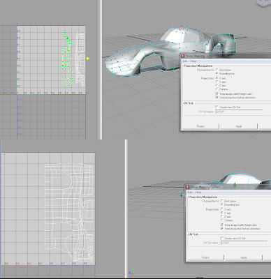
Conversion to SubD proved to be quite destructive for the UVs as lines are mapped onto curved lattices and the tessellation is adaptive.

I used a Subdiv proxy instead, which was easier to control because of the regular tessellation. Next few screen shots show creasing on some of the edges and vertices.

With the final structure of the fully defined I moved to creating the frames for the windscreens using extrusion and later the windscreens themselves. We can also see some of the early renders.

Next I added some chrome details using lofted curves on the mesh and then extruding the polygons on them. I also added some interior, which simply serves to prevent the car from looking as an empty shell.


The geometry is finally finished, as we can see from the render below.

Next I added bump mapping and did refinements on the color texture mapping. To do this, I had to unwrap the UVs, as bump mapping in Maya uses world coordinates in combination with UVs and therefore did display properly on the mirrored side of the body. The screenshots shown the final UV setup for the bump map and color map

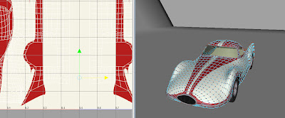
I will not go into more details about the texturing process, since is not part of the assignment. I'll just state that it took a surprisingly big amount of the time (more than 30% of the total.
With the model done it was time to render it. The materials in use are just basic blin for body, anisotropic for the chrome parts and transparent glass with index of refraction around 1.4. As all materials are highly reflective, I added some objects to the scene to be reflected into the car. First, a background was added, similar to a backdrop used in photo studios that doesn't have any visible sharp edges. In addition I added two stripes to further pronounce the shape of the body. For lighting, I used a simple three light setup with area lights and multisample shadows. All of this can be seen on the screenshot.

The final addition was a slight tint if green in the glass material, as this draft renders shows.

Done using an Intous 4 Wacom Tablet and Maya 2009.
What follows is not really a tutorial, but more a "making of". I'm not a 3D artist nor an expert on Maya, but I will try to answer any questions. I will start with the making of the wheels that will be used later. For this purpose I had set up an image projection for the side view and added tubes showing the rough dimensions of the tire and rim.
Then I drew a profile curve, revolved it into a tire and set up a cylindrical UV texture coordinate, needed for bump mapping.
Next I used revolve to create the rim, the axel of the rim and then a cylinder for the rim spike.
I cloned 32 spikes using Duplicate Special to create the complete rim.
I added "Gametechnology" text as a tire brand and bended it.
With the wheel done, I moved to the handle for opening the bonnet. As the handle is small and does not need to be modeled in much detail, I used polygon operations on a box to get the basic shape and then applied smooth to it. I started with a box and then pulled the vertices the get the silhouette
I then extruded the top faces and re-sized them.
And finally, I extruded the actual handle part of it.
With the small details done, it's time to move on to the body of the car. There are royalty free schematics on the internet for most cars, even exotic ones like the 1954 Fiat Turbine. I used three projections, one for each view.
In hope to work with NURBS, I drew the cross sections of the car.
After few tries with NURBS, I decided to leave that to the industrial designers around the world and other skilled professionals and move on to SubD surfaces. I used Loft to join the cross sections and get a polygonal mesh, which provided a better starting point then a simple box.
The next few steps show the process of refining the mesh into the car shape using just few operations like extrude, remove, append, split and merge vertex.
I also cut off the faces where the windscreen and windows will be. The original faces were curved along both axes which is usually not the case for glass, especially not in the 50's. This is very important for realistic reflections and refractions, so I decided to model them later instead of using the faces already there.
Conversion of the model into SubD showed that the topology of the model needs to be changed in order to get a smooth surface fitting the car. All the faces with more than four vertices needed to be modified and while keeping as regular structure as possible. Triangles and vertices shared by more than 4 edges were not my friend as they can break the surface too.
Next I created the windows from the refined mesh.
Early in the making of the model I decided to use bump map for some of the small details in the body instead of the modeling them. Having the low polygon mesh, I thought it would be the best time to create the UV coordinates. I used manual selection of faces and planar projection on them the get the basic layout and then manually stitch them in the UV editor.
Conversion to SubD proved to be quite destructive for the UVs as lines are mapped onto curved lattices and the tessellation is adaptive.
I used a Subdiv proxy instead, which was easier to control because of the regular tessellation. Next few screen shots show creasing on some of the edges and vertices.
With the final structure of the fully defined I moved to creating the frames for the windscreens using extrusion and later the windscreens themselves. We can also see some of the early renders.
Next I added some chrome details using lofted curves on the mesh and then extruding the polygons on them. I also added some interior, which simply serves to prevent the car from looking as an empty shell.
The geometry is finally finished, as we can see from the render below.
Next I added bump mapping and did refinements on the color texture mapping. To do this, I had to unwrap the UVs, as bump mapping in Maya uses world coordinates in combination with UVs and therefore did display properly on the mirrored side of the body. The screenshots shown the final UV setup for the bump map and color map
I will not go into more details about the texturing process, since is not part of the assignment. I'll just state that it took a surprisingly big amount of the time (more than 30% of the total.
With the model done it was time to render it. The materials in use are just basic blin for body, anisotropic for the chrome parts and transparent glass with index of refraction around 1.4. As all materials are highly reflective, I added some objects to the scene to be reflected into the car. First, a background was added, similar to a backdrop used in photo studios that doesn't have any visible sharp edges. In addition I added two stripes to further pronounce the shape of the body. For lighting, I used a simple three light setup with area lights and multisample shadows. All of this can be seen on the screenshot.
Done using an Intous 4 Wacom Tablet and Maya 2009.
Wednesday, March 10, 2010
Tracing Boxes
This is my last post on ray tracing, and it’s on tracing boxes. Spheres alone are not all that fun and the infinite planes have the drawback of being...well infinite. Therefore, I decided to put boxes to my ray tracer. It is of course possible to use 12 triangles. This is a general solution but it is not exactly cost effective and moreover, it does not scale well to collision detection, where boxes are often used (I am working on some physics code too). I started my journey by searching the web and of course, Real-Time Collision Detection by Christer Ericson, which is probably the best book in its field. What I got was plenty of fast algorithms that only tell if the there is an intersection or not, some of which give the intersection position too. Also few algorithms that give the normal vector as well, but most of them did checking against all 6 planes and went through lots of boundary conditions. As a normal vector is needed in ray tracing for light calculation, I decided to make the best of the both worlds.
The idea is very simple. Use the fast algorithm to get the intersection position and then use that information to get the normal. Say we have an axis aligned unit cube centered at the origin, a point on it and a vector to that point. The surface normal at that point is in the direction in which the vector extends the most. In case it’s not immediately obvious, let’s take one side of the cube, say the one laying on the x=1 plane. The side can be defined as an intersection of the x=1 plane and the cone made of half-spaces defined by x>|y| and x>|z|, which is exactly the same as the original statement. So now we have three steps of the algorithm.

The algorithm assumes that the box is axis aligned. This is not really an issue, as you can always do the intersection in the local space of the box. Transform the ray to the local space of the box with the inverse of rotation matrix of the box, find the intersection and normal and transform them back to world space with the rotation matrix of the box. Just have in mind that if you have scaling and translation applied to the box, the direction of the ray and the normal of the surface need special care.
The idea is very simple. Use the fast algorithm to get the intersection position and then use that information to get the normal. Say we have an axis aligned unit cube centered at the origin, a point on it and a vector to that point. The surface normal at that point is in the direction in which the vector extends the most. In case it’s not immediately obvious, let’s take one side of the cube, say the one laying on the x=1 plane. The side can be defined as an intersection of the x=1 plane and the cone made of half-spaces defined by x>|y| and x>|z|, which is exactly the same as the original statement. So now we have three steps of the algorithm.
- First, calculate the position of the center of the box and calculate the vector from it to the point on the surface.
- Next, scale the vector into a unit cube, to cancel the scaling of the box along the axes.
- Finally, zero out the coordinates with smaller absolute value, and then normalize the resulting vector.
This might not be the fastest algorithm, but it beats most that I have come across on the internet. Here is one very ugly image showing ray tracing of a box in room and some normal mapping. Also the scene from the post on ambient occlusion was modeled with some boxes and a sphere.
public class Box extends Traceable {

protected Vec3;
protected Vec3 max;

// Component-wise min
public static Vec3 min(Vec3 a, Vec3 b) {
return new Vec3( min(a.x, b.x),
               min(a.y, b.y),
               min(a.z, b.z));
}

// Component-wise max
public static Vec3 max(Vec3 a, Vec3 b) {
return new Vec3( max(a.x, b.x),
               max(a.y, b.y),
               max(a.z, b.z));
}

@Override
public IntersectionInfo intersect(Ray r) {
// Interval based test
Vec3 direction = new Vec3(r.direction);
direction.normalize();
//
Vec3 oneoverdir = new Vec3(1.0f / direction.x, 1.0f / direction.y, 1.0f / direction.z);
Vec3 tmin = min.minus(r.origin).times(oneoverdir);
Vec3 tmax = max.minus(r.origin).times(oneoverdir);
//
Vec3 realmin = min(tmax, tmin);
Vec3 realmax = max(tmax, tmin);
//
float minmax = min(min( realmax.x, realmax.y), realmax.z);
float maxmin = max(max( realmin.x, realmin.y), realmin.z);

if(minmax >= maxmin && maxmin > 0.0f) { // Have intersection
 // Get position
 float t = maxmin;
 Vec3 position = r.origin.add(direction.times(t));

 // Get normal
 // 1. Get vector to relative position
 Vec3 center = max.add( min ).times(0.5f);
Vec3 normal = position.minus(center);

 // 2. Scale to matching unit box
 normal.x /= max.x - min.x;
 normal.y /= max.y - min.y;
 normal.z /= max.z - min.z;

 // 3. Keep the largest axis
 if(Math.abs(normal.x) > Math.abs(normal.y)) {
    normal.y = 0.0f;
    if(Math.abs(normal.x) > Math.abs(normal.z))
       normal.z = 0;
    else
       normal.x = 0;
 } else {
    normal.x = 0;
    if(Math.abs(normal.y) > Math.abs(normal.z))
       normal.z = 0;
    else
       normal.y = 0;
 }
 // 4. Normalize to unit
 normal.normalize();
 return new IntersectionInfo(position, normal, t, this);
}
//
return new IntersectionInfo(false);
}
} // end class

Monday, January 4, 2010
Ambient Occlusion
Ambient Occlusion is a cheap and simple way to add global illumination effect to an rendered image, especially for a ray tracer. This adds depth and realism to the image. The sample below shows the difference.
An image rendered with ambient occlusion.

An image rendered without ambient occlusion.

The technique is as fake as it is straight forward, but if it's good enough for Pixar should be good enough for most purposes. Ambient occlusion for certain surface point is calculated by measuring how much light is blocked by it's surroundings. In a ray tracer this is done by casting rays from the surface point in all directions and counting how many hit the scene. In the following implementation we can also limit the radius if needed and the amount of shadowing due to occlusion.
int smp = Tracer.ambientOcclusionSamples;
int c = smp;
for(int i = 0; i < smp; i++) {
   Vec3 dir = Vec3.randomOnHemisphere(nearestHit.normal);
   dir = dir.times(Tracer.occlusionRadius);
   Vec3 org = nearestHit.location;
   Ray feeler = new Ray(org, dir);
   if( feeler.hit( nearestHit.object ) )
      c--;
}
color = color.times(1.0f - Tracer.occlusionAmount) .add( color.times((c * Tracer.occlusionAmount) / (float)smp) );
Most of the code should be staright forward and easy to understand only the Vec3.randomOnHemisphere(nearestHit.normal); function requires some explanation. As the name states, this function returns a vector, uniformly distributed on the unit hemisphere above the given vector. This is achieved by trail and error; we create random vectors in a unit cube and discard the corers to get uniform distribution on a unit sphere and than discard all the vectors not facing the same way as the given vector using a dot product test.
public static Vec3 randomOnHemisphere(Vec3 direction) {
   // Cut off the corners of the cube
   Vec3 v;
   do {
   v = new Vec3(
      2 * (float)Math.random() - 1,
      2 * (float)Math.random() - 1,
      2 * (float)Math.random() - 1);
   } while(v.length() > 1.0f && v.dot(direction)
   v.normalize();
   return v;
}
On average, no more than two thirds of the vectors are discarded. This might not be the most efficient method, but it does not require any vector transformations and matrix multiplication. Another way to achieve the same effect is to use a precalculated set of vectors distributed on the vertices of a regular polyhedron and transform it to face in the given direction. In a addition a random rotation around the main axis will remove the artifacts of using the same set of vectors.
UPDATE: It seams that this article is getting a lot more attention during the semester, so what better date to make a small correction than beginning of September.
The above method treats all rays shoot from the a certain point equally, while actually they don't contribute to the illumination of that point equally. Instead their contribution needs to be weighted by the dot product of the ray direction with the normal at that point, according to the cosine law.
I have the original sources for the tracer, but have lost the scene files. If I find them and find some time I might post an updated version of the code and a better looking image.
UPDATE: It seams that this article is getting a lot more attention during the semester, so what better date to make a small correction than beginning of September.
The above method treats all rays shoot from the a certain point equally, while actually they don't contribute to the illumination of that point equally. Instead their contribution needs to be weighted by the dot product of the ray direction with the normal at that point, according to the cosine law.
I have the original sources for the tracer, but have lost the scene files. If I find them and find some time I might post an updated version of the code and a better looking image.
Tuesday, November 10, 2009
Reflection and Refraction
After some tinkering with the stats, I got some interesting finds. Many people coming across this blog were searching for "cream pasta", but more importantly, the rest 75% were actually searching for ray tracing topics, especially reflection and refraction. While the image from the last post beautiful as it is, it does not give too much info. Some Java code snipets should help a bit more.
Now reflection is fairly simple. The angle between the reflected ray and the normal is the same as the angle between the incoming ray and the normal.
With some lengthy transformations we can get a formula for the direction of the refracted ray that contains the same condition, defining total internal reflection, as Snell's law. Thus, when the flowing method can't calculate the direction total internal reflection has occurred.
Now reflection is fairly simple. The angle between the reflected ray and the normal is the same as the angle between the incoming ray and the normal.
Calculating the direction of the ray after refraction is a bit more involved. We start with Snell's Law, stating that ratio of the sines of the angles of incidence and refraction is equivalent to the opposite ratio of the indices of refraction, to get the direction of the refracted ray. The outgoing angle is obviously not always defined with this formula, which bring us to the next phenomena. When the light is traveling from a medium with higher optical density to a medium with a lower one and the incident angle is larger than the critical angle total internal reflection occurs and no light leaves the medium. In fact some light is almost always reflected and the amount is governed by the Fresnel equations. In my implementation I just approximate the amount with the dot product (with complete disregard for all the complexities, not to mention frequency and polarization), but the visual result is good.
public static Vec3 reflect(Vec3 normal, Vec3 incident) {
float cosTheta = normal.dot(incident);
return incident.minus( normal.times(2 * cosTheta) );
}
With some lengthy transformations we can get a formula for the direction of the refracted ray that contains the same condition, defining total internal reflection, as Snell's law. Thus, when the flowing method can't calculate the direction total internal reflection has occurred.
I hope that was more insightful. Feel free to drop a comment.
public static Vec3 refract(Vec3 normal, Vec3 incident, float n1, float n2) {
 float dn = incident.dot(normal);

 float c = 1 - ((n1*n1)*(1-dn*dn) ) / (n2*n2);
 if(c < 0)
  return null;

 Vec3 t = incident.minus( normal.times( dn ) ).times( n1/n2 )
  .minus(
  normal.times( (float)Math.sqrt(c)) );

 return t;
}
Saturday, October 3, 2009
Tracing Rays
I have never considered simple rays more precious than I do now and not just because I am building a ray tracer, but because I have recently moved Utrecht, Netherlands and sunlight is a scarce commodity here. I missed the thrill of long lectures and midterm exams, so am student yet again! Game and Media Technology postgraduate at Utrecht University and so far it's great. This brings me back to my ray tracer and no ray tracer is complete without a Cornell Box and some balls, exhibit below:

It sports a vast number of very basic features (hugely popular in ray tracers from the early 90's) like:
- Phong materials
- Anti-aliasing
- Light reflection
- Light refraction (with Fresnel reflection)
- Area light and soft shadows
- Soft reflections
- and more to come!
The policy of the university on source sharing is "No." so no code pasting this time, but I am open for questions and discussion. I don't think too many people will find the code useful anyhow and plus you can always download POV ray, which is a world class open source ray tracer.
Wednesday, April 1, 2009
Last.fm and Spinach Pasta
The latest news from Last.fm says that users who are in countries other than USA, UK and Germany will have to subscribe for €3.00 per month for listening to Last.fm Radio. I am not too happy about this, generally because I have discovered a whole bunch of new bands and musicians with Last.fm, even with the very limited selection of songs the service has. In fact lets make an experiment. Go to http://www.last.fm/listen and waste one of your 30 trail plays by typing "Hot Action Cop". I bet "Fever The Flava" will start in few seconds. It is a cool song, but gets a bit old after ten times in the same day. Now €3.00 is not really that much in some countries but the again in some it might be, and the selectiveness is just plain not cool. Being bought up in half country, half zoo one might think that I should have grown immune to any discrimination coming my way, but somehow this bothers me.
Now so far this post has been somewhat informative, but not really helpful. But instead of geeky advices on how to get streaming music now when last.fm has gone all sour, I will tell you what else you can do with €3.00. How about a nice spinach and cream pasta.*

Preheat the oven to 200ºC (473 K). Boil some pasta, preferably whole wheat pasta for this one, in a big bowl. Throw about 150 gr of spinach into a sauce pan and drizzle it with olive oil. Add just a bit of garlic and salt. When the spinach is soft, but still bright green add some white cheese or alternatively some feta cheese. After a minute of stirring, add some cream. As soon as the cream gets homogeneous, reduce the heat to very low and let it simmer. The pasta should be done by now, so drain it and mix it with the creamy sauce. Add some freshly grounded pepper and grated parmesan. Put it in the oven for 20 minutes. Bon appétit!
*Note that the quantities and costs are per serving. The total cost of the meal may vary with to electricity prices and hence country.
Now so far this post has been somewhat informative, but not really helpful. But instead of geeky advices on how to get streaming music now when last.fm has gone all sour, I will tell you what else you can do with €3.00. How about a nice spinach and cream pasta.*

Preheat the oven to 200ºC (473 K). Boil some pasta, preferably whole wheat pasta for this one, in a big bowl. Throw about 150 gr of spinach into a sauce pan and drizzle it with olive oil. Add just a bit of garlic and salt. When the spinach is soft, but still bright green add some white cheese or alternatively some feta cheese. After a minute of stirring, add some cream. As soon as the cream gets homogeneous, reduce the heat to very low and let it simmer. The pasta should be done by now, so drain it and mix it with the creamy sauce. Add some freshly grounded pepper and grated parmesan. Put it in the oven for 20 minutes. Bon appétit!
*Note that the quantities and costs are per serving. The total cost of the meal may vary with to electricity prices and hence country.
Subscribe to:
Posts (Atom)