Showing posts with label render. Show all posts

Sunday, October 23, 2011

Building Your Own Game Engine - Graphics

This is the last one in the series of articles that go through the architecture of a small game engine for a small game, The Jelly Reef. The very last thing that was implemented into the game was the graphics. The art team in the first weeks of development was looking for the right look for the game. In mean time the our designer was looking for the right feel, we decided give this top priority and started writing the gameplay code and all the infrastructure. The graphics would wait up until we know what the game will be and look like.

With four talented drawing artist on the team, we knew that the game will be hand painted for the most part and that we will use sprite sheets for all the animations. You would expect this to lead to a 2D rendering system. After all, the math in all previous articles was 2D and Vector2D's were all over place. But at the same time we wanted to have some depth to our top down perspective and considered using parallax effect to achieve that. Using parallax would have some drawbacks and might be difficult to tweak or draw art for. Instead we opted against it, so the rendering system is actually a 3D one. There is a 3D projective camera and 3D triangles are being send to the GPU so the depth is inherent.

The goal was to have a system that can render static images in layers that would make up the level, some animated sprites for the object in the game and lots of bubbles. All this without killing performance, of course. Almost everything is drawn alpha blended, but some things like the GUI overlay and seaweed would require special treatment. Additionally we also wanted to be able to scale and tint all the sprites.
In the core of our graphics system is the RenderJob which the only thing that our render manager can render. From its fields it's very clear how we implemented the needed functionality.
public enum RenderPass { AlphaTested,
                         AlphaBlended,
                         Overlay }

// All the data need for rendering a object on screen
// A class rather than a struct to enable reference storing
public class RenderJob : IComparable<RenderJob>
{
  // In which pass should the geometry be rendered
  public RenderPass RenderPass;

  // Used for depth sorting in alpha-blended jobs
  public float Height;

  // The vertices in world or model coordinates
  public VertexPositionTexture[] Vertices;

  // Indices of the vertices
  public int[] Indices;

  // If vertices are in model coordinates a suitable transform
  // matrix should be submited, if vertices are in world
  // coordinates the identity matrix should do fine
  public Matrix WorldMatrix;

  // A texture to draw this geometry with
  public Texture2D Texture;

  // Allows the texture to be tinted with a solid color
  public Vector4 Tint;

  // Allows a render job to disable the caustics
  public bool DisableCaustics;

  // Create new render job
  public RenderJob()
  {
    Tint = new Vector4(1, 1, 1, 1);
  }

  // Compares two render jobs
  public int CompareTo(RenderJob other)
  {
     if (Height > other.Height)
       return 1;
     if (Height < other.Height)
       return -1;
     return 0;   // ==
    }
}
The rendering in our game is handled by the rendering manager and all entities that would like to be rendered need to implement the IRenderable inteface.
public interface IRenderable
{
  IEnumerable<RenderJob> GetJobs();
}
The manager simply goes over all the entities and fills up three lists, one for each render pass. The list with Alpha blended jobs gets sorted by height, from the lowest to the highest. Then the lists are rendered in the order they were declared in the enum aboove.

Each level can have up to five layers and they are rendered as any other alpha blended job. The height, and hence the parallaxing amount, can be set for each layer. The size is automatically determinate to fit the level size with some clearing for the parallaxing. The level layers can be drawn as layers in Photoshop. In the game, their alignment at the the middle of the screen would be the same as while drawing. This means that parallaxing does not interfere with gameplay. The game take place underwater. I really wanted for us to get that feeling early on by adding water caustics and started looking for real-time solutions on the subject. In the end none of the options looked convincing enough and many were too computationally expensive. We quickly opted for a precalculated sequence of images that tile in both, space and time. The image is applied in the shader and the strength of the effect can be tweaked per level. The shader also scales the effect with depth, adding another subtle depth cue.

This wraps up the articles series. I hope people will find them useful. If anyone needs more info, you can drop a comment below the article.

A new version of the engine is already in the making. It's based on a somewhat different concept, written in C++ and trying to be as platform independent as possible.

Thursday, March 18, 2010

Fiat Turbina - The Making of

It seems that I have one more post on ray-tracing, but now for something a bit different, a 1954 Fiat Turbina. I have chosen this model because of few reasons. It is sufficiently complex and there can be many approaches on how to model it. Equally important, it was the most aerodynamic shape of a car for 30 years, powered by a gas turbine yet technologically and commercially a complete failure, making it somewhat romantic.


What follows is not really a tutorial, but more a "making of". I'm not a 3D artist nor an expert on Maya, but I will try to answer any questions. I will start with the making of the wheels that will be used later. For this purpose I had set up an image projection for the side view and added tubes showing the rough dimensions of the tire and rim.


Then I drew a profile curve, revolved it into a tire and set up a cylindrical UV texture coordinate, needed for bump mapping.


Next I used revolve to create the rim, the axel of the rim and then a cylinder for the rim spike.


I cloned 32 spikes using Duplicate Special to create the complete rim.


I added "Gametechnology" text as a tire brand and bended it.


With the wheel done, I moved to the handle for opening the bonnet. As the handle is small and does not need to be modeled in much detail, I used polygon operations on a box to get the basic shape and then applied smooth to it. I started with a box and then pulled the vertices the get the silhouette


I then extruded the top faces and re-sized them.


And finally, I extruded the actual handle part of it.


With the small details done, it's time to move on to the body of the car. There are royalty free schematics on the internet for most cars, even exotic ones like the 1954 Fiat Turbine. I used three projections, one for each view.


In hope to work with NURBS, I drew the cross sections of the car.


After few tries with NURBS, I decided to leave that to the industrial designers around the world and other skilled professionals and move on to SubD surfaces. I used Loft to join the cross sections and get a polygonal mesh, which provided a better starting point then a simple box.


The next few steps show the process of refining the mesh into the car shape using just few operations like extrude, remove, append, split and merge vertex.


I also cut off the faces where the windscreen and windows will be. The original faces were curved along both axes which is usually not the case for glass, especially not in the 50's. This is very important for realistic reflections and refractions, so I decided to model them later instead of using the faces already there.


Conversion of the model into SubD showed that the topology of the model needs to be changed in order to get a smooth surface fitting the car. All the faces with more than four vertices needed to be modified and while keeping as regular structure as possible. Triangles and vertices shared by more than 4 edges were not my friend as they can break the surface too.


Next I created the windows from the refined mesh.


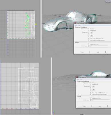
Early in the making of the model I decided to use bump map for some of the small details in the body instead of the modeling them. Having the low polygon mesh, I thought it would be the best time to create the UV coordinates. I used manual selection of faces and planar projection on them the get the basic layout and then manually stitch them in the UV editor.


Conversion to SubD proved to be quite destructive for the UVs as lines are mapped onto curved lattices and the tessellation is adaptive.


I used a Subdiv proxy instead, which was easier to control because of the regular tessellation. Next few screen shots show creasing on some of the edges and vertices.


With the final structure of the fully defined I moved to creating the frames for the windscreens using extrusion and later the windscreens themselves. We can also see some of the early renders.


Next I added some chrome details using lofted curves on the mesh and then extruding the polygons on them. I also added some interior, which simply serves to prevent the car from looking as an empty shell.


The geometry is finally finished, as we can see from the render below.


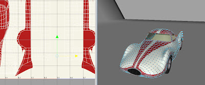
Next I added bump mapping and did refinements on the color texture mapping. To do this, I had to unwrap the UVs, as bump mapping in Maya uses world coordinates in combination with UVs and therefore did display properly on the mirrored side of the body. The screenshots shown the final UV setup for the bump map and color map


I will not go into more details about the texturing process, since is not part of the assignment. I'll just state that it took a surprisingly big amount of the time (more than 30% of the total.

With the model done it was time to render it. The materials in use are just basic blin for body, anisotropic for the chrome parts and transparent glass with index of refraction around 1.4. As all materials are highly reflective, I added some objects to the scene to be reflected into the car. First, a background was added, similar to a backdrop used in photo studios that doesn't have any visible sharp edges. In addition I added two stripes to further pronounce the shape of the body. For lighting, I used a simple three light setup with area lights and multisample shadows. All of this can be seen on the screenshot.


The final addition was a slight tint if green in the glass material, as this draft renders shows.


Done using an Intous 4 Wacom Tablet and Maya 2009.